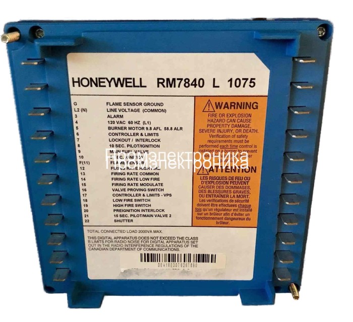
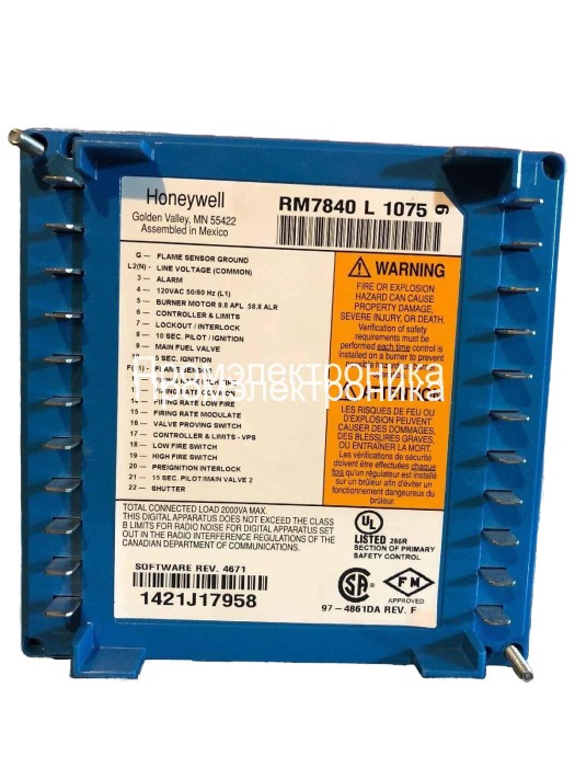
Honeywell RM7840L1075
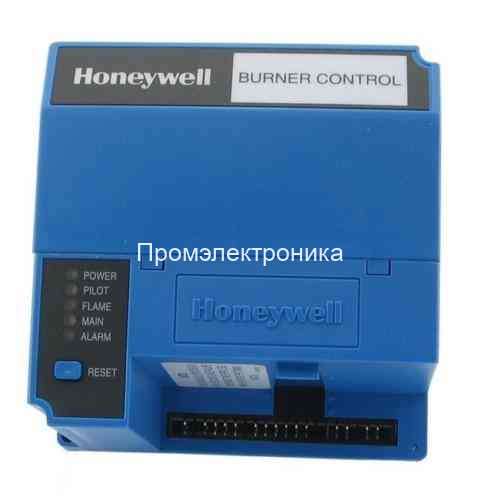

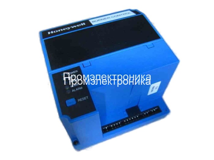


Контроллер Honeywell RM7840L1075 - это релейный модуль основанный на микропроцессоре. Предназначены для автоматического розжига газовых, нефтяных , а также горелок на комбинированном топливе.
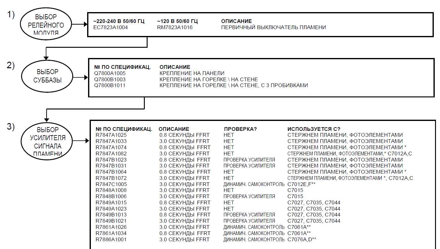
Необходимые компоненты системы :
- Релейный Модуль RM7840L1075
- Суббаза Q7800
- Усилитель.
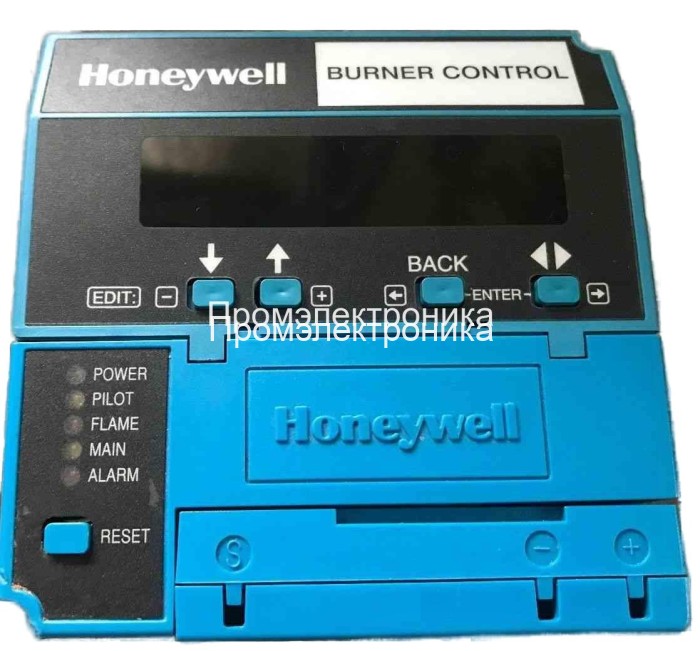
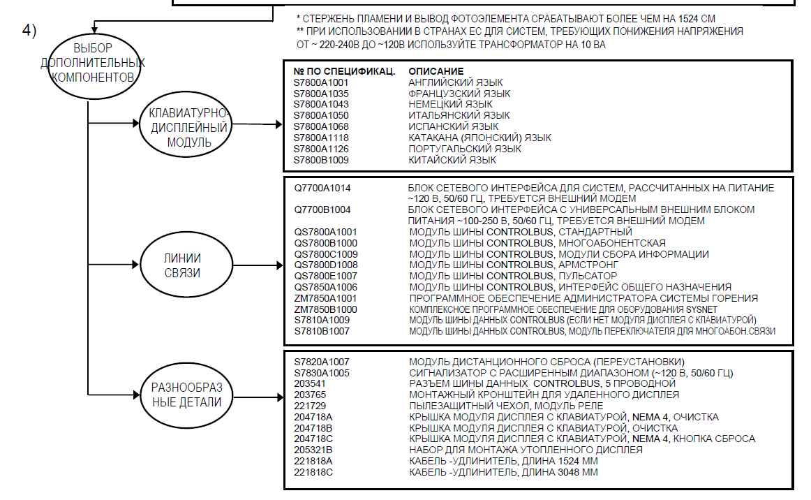
Дополнительные компоненты могут быть следующими: клавиатурно-дисплейный модуль, интерфейс персонального компьютера, модуль передачи данных, удаленный дисплейный модуль,программное обеспечение – COMBUSTION SYSTEM MANAGERa и другие.
Контроллер Honeywell RM7840L1075 обеспечивает мониторинг пламени, световую индикацию режима, системную или само-диагностику и поиск неисправностей.
Бренды | Honeywell |
Помогите другим пользователям с выбором - будьте первым, кто поделится своим мнением об этом товаре.
КОНТРОЛЬ СОСТОЯНИЯ АППАРАТНЫХ КОМПОНЕНТОВ ОБОРУДОВАНИЯ
Релейный модуль RM7840L1075 проверяет полярность карты продувки для предотвращения смещения времени продувки и отказов цепи. Он также проверяет, не повреждены ли переключатели конфигурации и аппаратные компоненты. Светодиод POWER мигает каждые 4 секунды, что является признаком выполнения теста оборудования.
ТЕСТ ЛОГИЧЕСКИХ СХЕМ
Этот тест проверяет целостность всех критичных нагрузок, клемм 8, 9, 10 и 21. Если нагрузки не запитываются правильно; например, на клемму клапана магистрали во время ПРОДУВКИ подается напряжение, то RM7840L1075 будет заблокирован при выполнении безопасного отключения. RM7840L1075 реагирует на изменения на входе и в то же время не допускает ложного отключения. Для правильной работы в условиях обычных электрических помех (например, скачков напряжения) на входе линии напряжения выполняется обработка сигналов. Обработка сигналов нечувствительна к синхронным помехам (шумам в линии, возникающим в одно и то же время во время каждого цикла линии).
ДИНАМИЧЕСКИЙ AMPLI-CHECK™
Динамический тест цепи AMPLI-CHECK™ проверяет работу усилителя работы пламени во время работы горелки и отключает RM7840L1075 при сбое усилителя.
Динамическая проверка УСИЛИТЕЛЯ ПЛАМЕНИ И ЗАСЛОНКИ
При самотестировании цепи 12 раз в минуту проверяются все электронные компоненты системы обнаружения пламени и в случае обнаружения ошибки RM7840L1075 отключается.
ДИНАМИЧЕСКИЙ ТЕСТ ВВОДА
Выполняется проверка всех входный цепей системы с тем, чтобы убедиться, что RM7840L1075 способен правильно определить состояние внешних управляющих элементов, ограничителей и блокировок. Если при этом тестировании обнаруживается какой то сбой, то происходит защитное отключение и выдается сообщение об ошибке.
ТЕСТ ДИНАМИЧЕСКОГО ЗАЩИТНОГО РЕЛЕ
Проверяется способность динамического защитного реле открываться и закрываться. Также проверяется, могут ли при необходимости критически важные нагрузки, клеммы 8, 9, 10 и 21 обесточиваться логической схемой динамического самотестирования.
ДИНАМИЧЕСКОЕ САМОТЕСТИРОВАНИЕ ЗАЩИТНОЙ ЦЕПИ
Микрокомпьютер проверяет себя и соответствующую аппаратуру в то время, как система защитных реле тестирует работу микрокомпьютера. При возникновении сбоя микрокомпьютера или защитного реле, который препятствует нормальному выполнению процедуры самотестирования, произойдет безопасное отключение и критичная нагрузка будет обесточена.
Capable Rating for select 7800 series controls and flame detectors
Conversion Wiring Diagrams for RM7800
Honeywell Primary Control cross reference
Programmer Control cross reference
Promotional Materials Commercial Boiler Controls and Accessories
Promotional Materials Enhanced 7800 Series
RM7800L1087, RM7840G1022, RM7840L1075, EC7840L1014 relay modules with valve proving
Section 1: General Questions Applying to all 7800 Series
Q. Does Honeywell make 208 to 240 VAC versions of the 7800 Series?
A. Yes, but they are for export and would not be used in this country. All old 208 to 240 VAC systems should be upgraded to 120 VAC. Every insurance organization and approval body in the U.S.A. requires that flame safety systems be 120 VAC, one side grounded.
Q. The LED marked “Power” keeps blinking. Is this to attract attention that something is wrong?
A. No, the Power LED is supposed to blink every four seconds. This means the relay is checking itself internally.
Q. What is “Initiate?”
A. During the initiate period, all the 7800 Series of controls examine the voltage and frequency of the power supplied. The power must be within certain tolerances for the control to remain on line. All of the 7800’s are rated 120VAC, 60 HZ. The tolerances for voltage are plus 10%, minus 15% (102 to 132 Volts) and plus 0%, minus 10% for frequency (51 to 60 HZ). There are 50 HZ controls available.
Q. Is there an “Initiate” period on each call for heat?
A. No. The initiate period is activated when the relay is “initially” powered. The 7800’s should be powered through a fused disconnect so they are powered at all times. The 7800’s will also enter initiate at any time if the power supply goes out of tolerance.
Q. How long is the “Initiate” period?
A. All 7800’s are a minimum of 10 seconds. There was an exception to this. The original RM7890’s had only a two-second initiate period, but since October of 1994, the RM7890’s were revised and now have a 10 second minimum initiate period, like all the rest of the 7800 series.
Q. How long can initiate last?
A. That depends. If, on power-up, the initiate tolerances are not met within the 10 seconds, a “hold” period is started. If the tolerances are met during this “hold” period, the 10-second period re-starts to make sure all tolerances are met for 10 seconds. The “hold” period can last up to 4 minutes maximum. If tolerances are not met in 4 minutes, a lockout will occur.
Q. What’s the difference between safe-start check and initiate?
A. Initiate was explained in the preceding question. Part of the safe-start check is continuous in stand-by, and part happens every time there is a call for heat. Safe-start check looks for a flame signal at start-up, same as the old mechanical relays did, but now includes checking for a flame signal in standby. Also, on a call for heat, all the output terminals are momentarily turned into inputs for a load check. This takes from one to three seconds. If any output terminal “sees” 36 volts or more, the sequence will not continue and a lockout will occur. Programmers also check all the interlock circuits continuously during standby. All of these circuits, flames, and voltage checks are called the “expanded safe-start check.”
Q. Can I jumper terminal G to L2?
A. NO! This is prohibited in all electrical codes. Read and follow the number 1 footnote on page 2 of every 7800 Series relay instruction/specification sheet. This is very important.
Q. If hot (+) and N (-) are connected wrong, with the relay be damaged?
A. No. The relay recognizes the wiring error and locks out. If a display is used, fault codes 67 or 109 will appear.
Q. Can I reconnect a JR jumper on a relay that I mistakenly cut?
A. No, and Yes. First, remember that cutting a jumper does not make the relay inoperative. Clipping a jumper enhances the level of safety. Second, note that the jumpers are not just wires. They consist of a specific resistor. Honeywell does not recommend even trying to restore a clipped jumper. If any damage is done in trying to restore a clipped jumper, the warranty is void! Now, as to the “yes.” Yes, it has been done, using a small electric soldering gun and being very careful, but you’re on your own.
Q. Is there a case available for the S7800 display?
A. Yes, order part number 206311.
Q. How long should pre-purge be?
A. Long enough to result in four complete air changes through the burner. This can be calculated. One needs to know the CFM capacity of the burner/blower, the internal volume of the burner, the flue pipes, the vent pipes, and the chimney. In the real world of burner service, the needed information is seldom known. If a 7800 is being used to replace an existing control, use a purge card to match or exceed the old control’s purge timing.
Q. Are the 7800’s all Solid State, or are there mechanical relays still in them?
A. Mechanical relays are still used, but the coils and contacts are sealed to prevent dirt, dust, grease, or any contaminant from affecting them. The number of relays in a specific device can be determined by looking at Honeywell’s “Internal Block Diagram” for that device.
Q. Hoe many cycles can be expected for the 7800 Series?
A. The 7800’s meet the U.L. cycle test 10 years or 100,000 cycles. Honeywell actually tested to over 250,000 cycles!
SECTION 2: PRIMARIES
Q. Can a RM7890 be used with a standing pilot?
A. Yes, but a relay will have to be added. Connect the 120 VAC coil of a relay between terminals 8 and L2 of the Q7800 sub-base. Connect the pilot duty normally open contacts of the relay between the F terminal and the flame rod. There is an RM7890C1005 made only for standing pilot applications.
Q. Can a low voltage controller be used with the RM7890?
A. There is no 24 VAC low voltage source available in any 7800 Series control. When replacing an RA890 that used a low voltage thermostat connected to T and T terminals for the old Q270 base, and it is inconvenient to change to a line voltage controller, a 24 VAC coil relay and transformer can be added. Wire the relay coil and thermostat contacts in series on the low voltage side of the transformer. See Figure 1. The normally open contacts of the relay are connected between terminals 3 and 6 on the Q7800 base.

Figure 1.
Q. When using a 3 second flame response amplifier in an RM7895, must JR2 be clipped?
A. No. JR2 must only be clipped when using a 3 second flame failure response amplifier with the RM7890.
Q. How fast must the airflow switch contact close when using an RM7895?
A. It depends on the length of the purge card timing. Purge timing begins when terminal 4, the burner/blower motor is powered. If using the two-second-purge card, the airflow switch must close in 2 seconds. If using a 7 second purge timer, it must close in 7 seconds. With all other purge cards, 10 or more seconds; the airflow switch must close in 10 seconds.
Q. What happens if the airflow switch does not close in the allocated time?
A. It depends on how relay jumper JR3 is configured. If JR3 is left intact, the control will recycle to the beginning of purge. If the airflow switch fails to close again, the control will again recycle, in effect it will purge “forever.” It will not lockout! If JR3 is clipped, the control will lockout if the air flow switch does not close in the allotted time. This prevents continuous purge, should the airflow switch fail open.
Q. What happens if the air flow switch contacts weld or stick closed? (Same as jumping the air flow switch.)
A. This depends on the model of the RM7895 relay selected. The RM7895B and D have an airflow switch safe start check feature that detects a closed circuit between terminals 6 and 7. (Jumpered or welded contacts.) The sequence will not continue if this circuit is closed. The control will wait two minutes for this fault to clear. If the circuit remains closed for the two minutes, the RM7895B and D will lockout. There does not have to be a call for heat to activate this feature. It is active in standby. The RM7895A and C do not have this feature.
Q. Besides the airflow safe start check feature, what other differences are there in the RM7895’s?
A. Terminal 10, ignition, on the RM7895A, B, C, and D is either 4 or 10 seconds, depending on the configuration of jumper JR-1. On the RM7895A and B terminal 8, pilot, is an intermittent pilot. On the RM7895C & D, it is a 10 second interrupted pilot. The RM7895C & D have a terminal 21, delayed main valve. There is no powered terminal 21 on the RM7895A and B. All the rest of the terminals 5, L2, 6, 7, 9, 4, and 3 are the same on A, B, C, and D’s. (There are two seldom-used RM7895’s that have a different action on terminal 10. The RM7895A1047, and the RM7895C1020. Terminal 10 is de-energized as soon as flame is proven. The C1020 also has a fixed pilot of 10 seconds. No 4-second is available.)
SECTION 3: PROGRAMMERS
Q. Can an RM7840L be used in place of an RM7800L?
A. Yes. They wire the same and functionally, are the same. Any RM7840 E, G, L, or M is the same as its letter equivalent RM7800E, G, L, or M. The only difference is that the RM7800 includes an S7800A display module and the RM7840 has only a dust cover where a display can go.
Q. What other 7800’s come with the display module?
A. The RM7838’s.
Q. Will the RM7800’s and 7838’s work without the display?
A. The RM7838’s will work without the display. The RM7800’s will work without the display in a S7810A is used in place of the display. The S7800A display does not have to be wired to the S7810A.
Q. Does the S7800A display have any control of the relay functions?
A. Not really. If you consider the remote reset capability of the display as a control function, then the display has one controlling function. Otherwise, the S7800A reads the information stored in the relay module’s memory. This is important! Vast amounts of important information are stored in the relay module. As a service tool, the display is worth – well, it’s priceless!
Q. What happens if I remove the S7800A display from an RM7800 while the burner is on?
A. The burner will immediately shut down, and lockout will occur. The burner will post purge. If the display is removed from an RM7800 in standby, a lockout will occur.
Q. What is “Energy Saving Pre-Purge?”
A. This feature is found in the Rm7800E only. It means that the burner/blower motor is not energized until the high fire purge switch is closed. The energy saved is the electricity not used to run the burner/blower motor until the burner damper is wide open.
Q. What’s the difference between pre-ignition interlock and a low-fire start switch?
A. A pre-ignition interlock is any switch that must remain closed until pre-purge is completed. Typically, it is a fuel valve proof of closure switch. A low fire start switch is used to prove the firing rate valve motor is in the low fire position before and during ignition.
Q. When using the RM7800 or RM7840, if there is no pre-ignition interlock, what can I do?
A. Your best course of action would be to add one. You will have enhanced the safety of the system. Otherwise, you’ll have to jumper terminals 4 to 20 on the Q7800 base.
Q. Can the high fire purge switch and/or the low fire start switches be jumpered?
A. Yes, but you will add 30 seconds to the pre-purge timing for each switch jumpered.
Q. Can I add a high fire purge switch to an RM7800/7840G between terminals 5 and 19?
A. No. On the Rm7800/7840G terminal 19 is used to configure terminal 21, and main flame establishing period.
Q. When using the Rm7800/7840E or L, if the high fire purge switch doesn’t close, will the burner be in purge “forever?”
A. No. Unlike the R4140’s, the RM7800’s will wait for 4 minutes and 15 seconds for the switch to close, and then lock out. The same thing happens if the low fire start switch fails to close on all RM7800/7840.
Q. Just what are the differences between the RM7800/7840E, L, G, and M?
A. Surprisingly, this is one of the most asked questions. I say surprisingly because by comparing the chart that shows timing for normal operating and wiring diagrams, the differences become very evident.
See Figure 2. Note that timings for initiate, standby, purge, run, and post purge, are identical for all models.

Figure 2.
Now look at Figure 3. On the E and L, all terminal functions are the same. Note that the only difference between an RM7800E and RM7800L is how the H.F.P.S. is wired to terminal 19. On the E, it is between terminals 4 and 19, resulting in “energy saving purge.” On the L, the H.F.P.S. is between terminals 5 and 19.

Figure 3.
On the RM7800G, there is no H.F.P.S. Terminal 19 is used to configure terminal 21.
The RM7800M has no terminal 19, and no modulating firing rate valve circuit, terminals 12, 13,14, and 15 as on the E, G, and L’s. The M’s do have a switching circuit, terminals 13, 14, and 15. Most M’s are used on ON/OFF burners with no firing rate valve is a separate relayed circuit.
When using an M, many times there will be no L.F.S.S. The switching circuit can then be used to input terminal 18 rather than jumping terminals 18 and 5, thereby avoiding 30 seconds to pre-purge timing.
Figure 3 points out each terminal’s function and timing.
By studying Figures 2 and 3, the differences in programmers will be apparent, and the most economical programmer can be selected for a specific job.
Техническое описание: Модуль реле Honeywell RM7840L1075
Honeywell RM7840L1075 является частью серии 7800 релейных модулей — это микропроцессорные интегрированные контроллеры горелок, предназначенные для автоматического розжига газовых, жидкотопливных или комбинированных одногорелочных установок. Данный документ относится к моделям RM7800E,G,L,M и RM7840E,G,L,M, при этом RM7840L1075 является специфической моделью в рамках этой серии.
Применение Модули реле RM7800/RM7840 используются для двухпозиционного (On/Off) управления по стандартам UL/CSA, модулирующего управления по UL/CSA, а также для модулирующего управления по стандартам FM/IRI. RM7840L1075, как L-модель, ориентирован на применение в системах с двухпозиционным управлением.
Основные функции и компоненты Система RM7800/RM7840 включает в себя релейный модуль, модуль клавиатуры и дисплея (стандартно для RM7800, опционально для RM7840), пылезащитную крышку (стандартно для RM7840), цоколь, усилитель пламени и карту продувки. Модуль обеспечивает автоматическую последовательность работы горелки, контроль пламени, индикацию состояния системы, самодиагностику и помощь в поиске неисправностей. RM7840L является твердотельным аналогом для замены электромеханических контроллеров R4140.
Ключевые опции включают:
- Интерфейс для персонального компьютера.
- Модуль DATA CONTROLBUS MODULE™.
- Удаленный монтаж дисплея.
- Расширенный аннунциатор первого отказа.
- Программное обеспечение Combustion System Manager™.
Технические характеристики
- Электрические параметры:
- Напряжение и частота: 120 В переменного тока (+10/-15%), 50 или 60 Гц (±10%).
- Потребляемая мощность: RM7800/RM7840: 10 Вт максимум.
- Максимальная общая подключенная нагрузка: 2000 ВА.
- Предохранитель: 15 А максимум, тип SC или эквивалентный быстродействующий.
- Параметры окружающей среды:
- Рабочая температура: от -40°F до +140°F (от -40°C до +60°C).
- Температура хранения: от -40°F до +150°F (от -40°C до +66°C).
- Влажность: 85% относительной влажности, непрерывно, без конденсации.
- Вибрация: 0.5G.
- Сертификация и одобрения:
- Underwriters Laboratories Inc. Listed: File No. MP268, Guide No. MCCZ.
- Canadian Standards Association Certified: LR9S329-3.
- Factory Mutual Approved: Report No. J.I. 1V9A0.AF.
- IRI Acceptable.
- Federal Communications Commission, Part 15, Class B-Emissions.
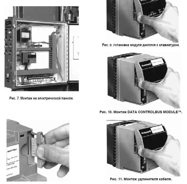
Монтаж и установка
- Установку должен производить обученный, опытный техник по обслуживанию систем безопасности пламени.
- Цоколь Q7800 может монтироваться в любом положении, кроме горизонтального с контактами, направленными вниз. Рекомендуется стандартное вертикальное положение.
- Необходимо обеспечить достаточный зазор для обслуживания и доступа к компонентам.
- Модуль RM7840L1075 устанавливается на цоколь Q7800 вертикально или горизонтально с ножевыми контактами, направленными вниз. При монтаже на Q7800A, модуль должен находиться в электрическом шкафу.
- Проводка должна соответствовать всем применимым кодам и нормам, включая NEC Class 1 (линейное напряжение).
- Не прокладывать высоковольтные провода трансформатора розжига в одном кабелепроводе с проводкой детектора пламени или модуля Data ControlBus Module™.
Последовательность работы (специфично для RM7840L) Модуль RM7840L следует определенной последовательности операций, включая инициализацию, режим ожидания, предпродувку, розжиг пилотной горелки (PFEP), розжиг основной горелки (MFEP), рабочий режим и постпродувку.
- Инициализация (Initiate): 10 секунд при подаче питания или при отклонении напряжения/частоты. При несоответствии параметров напряжения/частоты, контроллер переходит в режим удержания до 4 минут, после чего блокируется.
- Ожидание (Standby): Готовность к запуску при наличии запроса на тепло. Все контролируемые цепи должны быть в правильном состоянии.
- Предпродувка (Prepurge): Время продувки выбирается от 2 секунд до 30 минут. Для RM7800/RM7840E,L предпродувка не начнется, пока не замкнутся цепь блокировки (Lockout Interlock) и переключатель высокой мощности (High Fire Switch). Блокировка по предрозжигу (Preignition Interlock) должна оставаться замкнутой; в противном случае для RM7800/RM7840E,L произойдет защитное отключение. Блокировка (Lockout Interlock) должна замкнуться в течение 10 секунд предпродувки, иначе произойдет защитное отключение для RM7800/RM7840E,L. По завершении продувки привод регулирования мощности переводится в положение низкой мощности. Переключатель низкой мощности (Low Fire Switch) должен быть замкнут перед переходом к розжигу.
- Период розжига пилотной горелки (PFEP):
- Клапан пилотной горелки и трансформатор розжига (клеммы 8, 10 и 21) получают питание. RM7800/RM7840E,L имеют 15-секундный прерываемый пилотный клапан на клемме 21 и 10-секундный прерываемый пилотный клапан/розжиг на клемме 8. Для RM7840L1026 клемма 21 обеспечивает функцию прерывистого пилота.
- Пламя должно быть зафиксировано к концу 10-секундного PFEP (или 4-секундного, если перемычка JR1 удалена). Иначе – защитное отключение.
- Розжиг (клемма 10) отключается через 5 секунд для раннего прекращения искрообразования.
- Период розжига основной горелки (MFEP):
- Клемма 9 (главный топливный клапан) получает питание после подтверждения пламени в конце PFEP.
- Клемма 8 отключается через 10 секунд после запитывания клеммы 9.
- Действие клеммы 21 для RM7800E,L/RM7840E,L: обесточивается через 15 секунд после запитывания клеммы 9. Для моделей RM7800L1053 и RM7840L1026 клемма 21 остается под напряжением, пока есть запрос на тепло.
- Рабочий режим (Run): 10-секундный период стабилизации в начале. Привод регулирования мощности переходит в режим модуляции (для RM7800/RM7840E,G,L). Контроллер остается в рабочем режиме до тех пор, пока вход контроллера (клемма 6) не разомкнется.
- Постпродувка (Postpurge): 15 секунд после завершения рабочего режима. Главный топливный клапан и прерывистый пилотный клапан (клеммы 9 и 21) обесточиваются, а привод регулирования мощности переводится в положение низкой мощности. Блокировка предрозжига (Preignition Interlock) должна замкнуться в течение первых 5 секунд постпродувки.
Защитное отключение (Lockout) Защитное отключение происходит при различных условиях, таких как:
- Отсутствие или неисправность карты продувки.
- Изменение конфигурационных перемычек после 200 часов работы.
- Ошибки в электропитании переменного тока.
- Превышение 4-минутного периода инициализации.
- Наличие сигнала пламени в режиме ожидания (Standby) через 40 секунд.
- Разомкнутая блокировка предрозжига (Preignition Interlock) в режиме ожидания суммарно 30 секунд.
- Для RM7840E,L: размыкание блокировки предрозжига (Preignition Interlock) во время предпродувки.
- Для RM7840E,L: обнаружение сигнала пламени после первых 10 секунд предпродувки.
- Для RM7840E,L: переключатель высокой мощности (High Fire Switch) не замыкается в течение 4 минут 15 секунд после команды на высокую мощность в начале предпродувки.
- Переключатель низкой мощности (Low Fire Switch) не замыкается в течение 4 минут 15 секунд после команды на низкую мощность в конце предпродувки.
- Для RM7840E,L: блокировка (Lockout Interlock) не замыкается в течение 10 секунд в предпродувке или размыкается во время предпродувки, PFEP, MFEP или рабочего режима.
- Отсутствие пламени к концу PFEP или MFEP.
- Отсутствие пламени в рабочем режиме.
- Внутренние системные ошибки.
Конфигурационные перемычки (для RM7840L) RM7840L имеет возможность конфигурации через перемычки (JR1, JR3 для всех моделей).
- JR1 (PFEP): Не тронутая – 10 секунд; удалена – 4 секунды.
- JR3 (Проверка блокировок при запуске): Не тронутая – отключена; удалена – включена.
Это техническое описание основано на предоставленной документации для серии RM7800/RM7840, с акцентом на характеристики, применимые к L-моделям, таким как RM7840L1075. Конкретные детали работы для RM7840L1075 могут зависеть от его точной конфигурации и прикладных настроек, которые должны соответствовать указаниям производителя.
Для заказа оборудования Honeywell обращайтесь в отдел продаж:
Телефон для связи с отделом продаж и технической поддержкой:
8-800-333-19-98 (Бесплатный звонок из любой точки РФ)
Whatsapp, Telegram, Max:
+7958-623-59-59